CNC machining for robotic arms is the precision manufacturing process of producing joint housings, structural links, transmission gears, and end-of-arm mounting interfaces from engineering materials including 7075-T6 aluminum, 17-4PH stainless steel, and titanium Grade 5. Alloyer delivers CNC-machined robotic arm components in 1–1,000 piece batches with 72-hour standard lead time and integrated DFM review.
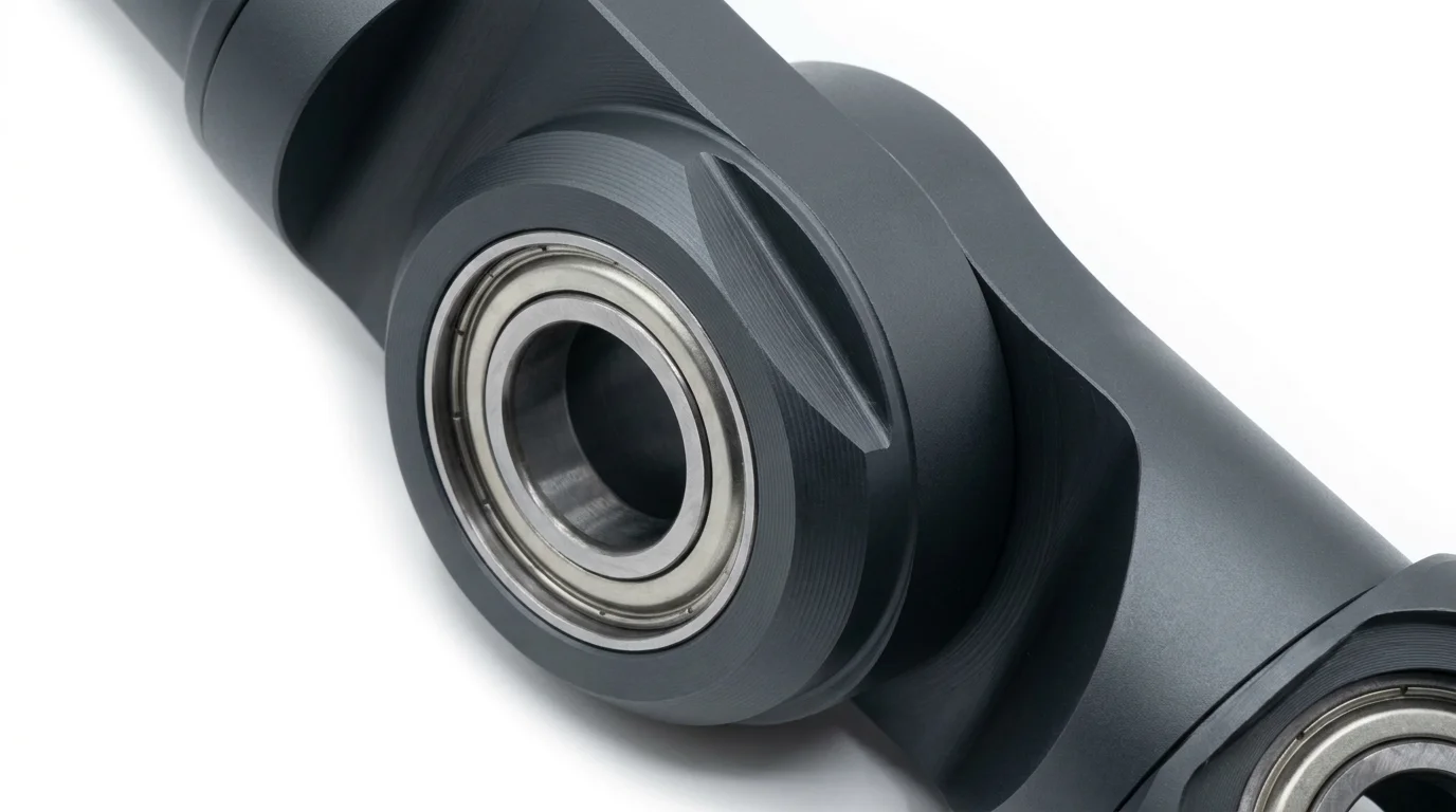 Caption: A 5-axis CNC-machined 7075-T6 aluminum robotic arm joint housing with Type III hardcoat anodized finish. Precision bearing bores machined to H6 tolerance. Alloyer delivers components like this in 5–7 business days.
Key Things to Know About CNC Machining for Robotic Arms
- Material selection scales with payload: 6061-T6 suffices for arms under 10 kg payload; 7075-T6 becomes the standard at 10–50 kg; and high-strength 17-4PH or Ti-6Al-4V enters the picture above 50 kg, where cyclic fatigue margins thin out.
- Tolerance stacking is the hidden cost driver: A 6-axis arm with 12 machined interfaces per link can accumulate 0.12–0.30 mm of total tolerance stack if each interface carries ±0.02 mm. Specifying H7 only where bearings mate and relaxing the rest to ISO 2768-m is the single most effective way to control machining cost.
- Cantilever loading demands material stiffness first, not just strength: An arm extending 1.5 m under a 20 kg payload deflects primarily in bending. Aluminum's elastic modulus (~69 GPa) versus steel (~200 GPa) means deflections are roughly 3× larger for the same cross-section — a factor that DFM pocketing patterns must account for.
- 5-axis machining cuts setup error in half: Robotic arm housings have bearing bores at compound angles. Machining all precision features in one 5-axis setup eliminates the ±0.03–0.05 mm re-fixturing error that accumulates across separate 3-axis operations.
- Batch size dictates machining strategy: At 1–10 pieces, soft jaws and manual setups dominate. At 50–200 pieces, dedicated fixture plates with hydraulic clamping recover their tooling cost within the first production run and reduce per-part time by 25–35%.
Why Robotic Arms Demand Specialized CNC Machining
Industrial robotic arms are manufacturing's workhorses — they weld car chassis at 2.0 m/s, assemble smartphones with 5 µm repeatability, and palletize 200 kg payloads 24/7. Each application pushes different CNC requirements.
Precision and Repeatability Across Millions of Cycles
A pick-and-place arm in semiconductor handling must hit the same position within ±0.01 mm after 10 million cycles — or it drops a wafer. This demands bearing bores machined to H6 or H7 tolerance with surface finishes of Ra 0.8 µm or better, achieved through precision boring followed by post-machining honing. Aluminum 7075-T6 is the dominant material here: its thermal expansion coefficient (23.6 µm/m·°C) is close to that of standard bearing steel (12–13 µm/m·°C for 52100), minimizing differential expansion effects that degrade bearing preload over temperature swings.
Cantilever Loading and Structural Stiffness
Every robotic arm is fundamentally a cantilever beam. The base joint carries not only the payload but also the weight of every subsequent link and motor. A 6-axis arm with a 20 kg payload and 1.5 m reach can generate over 1,500 N·m at the base joint under dynamic acceleration. The structural link connecting joints must resist bending without excessive deflection, which favors materials with high elastic modulus. For aluminum arms, this means deeper cross-sections and carefully placed ribbing — not wall thickening across the board, which adds weight and material cost without proportional stiffness gains.
Internal Cable Routing and Cooling Channels
Power cables, encoder feedback lines, and pneumatic tubes for end-effectors must pass through the arm structure. This means CNC-machined internal channels, pass-through bores, and cable management features integrated directly into the structural links. The machining challenge is achieving smooth internal surface finishes (Ra 3.2 µm minimum) on long bores — typically L/D ratios of 8:1 to 12:1 — where chip evacuation becomes the bottleneck. Gun drilling or EDM drilling are preferred over twist drilling for these features.
Material Properties for Robotic Arm Components
Metals — Structural and Transmission
| Material | Density (g/cm³) | Yield Strength (MPa) | UTS (MPa) | Elastic Modulus (GPa) | Machinability | Cost Index* | Typical Application |
|---|---|---|---|---|---|---|---|
| Al 6061-T6 | 2.70 | 276 | 310 | 68.9 | Excellent | 1.0× | |
| Al 7075-T6 | 2.81 | 503 | 572 | 71.7 | Good | 1.5× | |
| Al 7050-T7451 | 2.83 | 455 | 524 | 71.7 | Good | 1.7× | |
| SS 17-4PH H900 | 7.80 | 1,000 | 1,070 | 204 | Fair | 2.5× | |
| SS 440C | 7.65 | 450 | 760 | 200 | Difficult | 3.0× | |
| Ti-6Al-4V | 4.43 | 880 | 950 | 113.8 | Poor | 8.0× | |
| SAE 4140 | 7.85 | 655 | 1,030 | 205 | Good | 1.3× |
Polymers and Composites
| Material | Density (g/cm³) | Yield Strength (MPa) | Elastic Modulus (GPa) | Machinability | Cost Index* | Typical Application |
|---|---|---|---|---|---|---|
| POM (Delrin) | 1.41 | 65 | 2.8 | Excellent | 1.2× | |
| PEEK | 1.30 | 90–100 | 3.6 | Medium | 15.0× | |
| Nylon 6/6 GF30 | 1.37 | 160 | 9.0 | Good | 1.0× | |
| Carbon Fiber (T700) | 1.55 | — | 230+ (tensile) | Difficult | 5.0× |
Materials by Arm Segment: Joint-by-Joint Guide
Base Joint (J1)
The base takes the maximum bending moment and torque. For arms with payloads under 30 kg, Al 7075-T6 is the standard. For payloads 30–80 kg, the housing transitions to 17-4PH for fatigue life. Above 80 kg, base housings often become steel fabrications or cast-iron structures, with CNC machining reserved for precision bearing seats.
| Feature | Material | Rationale |
|---|---|---|
| Bearing seat | 17-4PH H900 | |
| Housing body | Al 7075-T6 | |
| Mounting flange | SAE 4140 |
Shoulder Joint (J2) and Elbow Joint (J3)
These joints experience high dynamic torque during rapid repositioning moves. The housing must be stiff enough to avoid deflection under peak acceleration (commonly 5–8 m/s² for high-speed arms).
| Component | Material | Why |
|---|---|---|
| Joint housing | Al 7075-T6 | |
| Torque tube | Al 7075-T6 or CF T700 | |
| Gearbox flange | SS 17-4PH |
Wrist Joint (J4/J5/J6)
The wrist endures lower loads but requires the highest precision: bearing bore tolerances for small Harmonic Drive units (CSF-14 to CSF-25) demand H6 or tighter.
| Component | Material | Why |
|---|---|---|
| Wrist housing | Al 7075-T6 or Al 7050 | |
| Output shaft | SS 17-4PH | |
| End-effector mount | Al 7075-T6 or Ti-6Al-4V |
Tolerances & Surface Finishes
| Feature | Tolerance | Surface Finish | Notes |
|---|---|---|---|
| Bearing bore (base/shoulder) | H6 (+0.016/0) | Ra 0.8 µm | |
| Bearing bore (wrist) | H6 (+0.011/0) | Ra 0.4 µm | |
| Gearbox pilot diameter | h6 (0/−0.016) | Ra 1.6 µm | |
| Seal contact surface | h7 | Ra 0.4 µm | |
| Housing mounting face | ±0.05 mm | Ra 3.2 µm | |
| Internal cable bore | ±0.1 mm | Ra 3.2 µm |
DFM Tips for Robotic Arm Parts
1. Cored internal features cut cycle time by 40%: Instead of machining a solid block into a hollow tube, start with a near-net-shape extrusion or cast preform and machine only the precision surfaces. This reduces roughing passes from 6 to 2 on a typical 500 mm upper arm link.
2. Specify H7 for bearing bores only: Every ±0.01 mm tolerance adds approximately 15–20% to machining cost per surface. Reserve H6/H7 for bearing seats and gearbox pilots; non-critical mounting faces can use ISO 2768-m (±0.1 mm), cutting total part cost by 25–35%.
3. Avoid sharp internal corners: Every inside corner requires a radius equal to at least 1.5× the cutter diameter. A 6 mm end mill leaves a 3 mm radius. For square corners (0 mm radius), switch to EDM wire cutting at 3–5× the cost of milling. Design for R4 or larger internal radii to stay in standard milling territory.
4. Plan for soft-jaw workholding at prototype quantities: At 1–10 units, dedicated fixture plates are not economical. Design each link with at least one parallel clamping surface and one datum bore that can be gripped in soft jaws. This saves $500–1,200 in tooling cost per unique part number.
5. Thread depth matters more than thread size: For high-vibration joints, thread engagement in aluminum must be at least 2.5× the bolt diameter to prevent thread stripping under cyclic loading. Alternatively, specify Helicoil inserts for all M4 and smaller threads in 7075-T6 housings.
Lead Times and Batch Pricing
| Batch Size | Lead Time | Per-Unit Cost (7075-T6 arm link, 300 mm) | Recommended Process |
|---|---|---|---|
| 1–5 units | 5 business days | $180–280 | |
| 10–50 units | 10 business days | $95–150 | |
| 100–500 units | 15–20 business days | $55–85 | |
| 500+ units | 25–30 business days | $40–65 |
FAQ
What is the best material for a robotic arm joint housing under 20 kg payload?
Aluminum 7075-T6 is the standard for light-to-mid-duty arms. It offers 503 MPa yield strength at 2.81 g/cm³ — the best strength-to-weight ratio in the aluminum family. For heavier payloads (30 kg+), transition to 17-4PH stainless steel for the housing body, which provides 1,000 MPa yield at 7.80 g/cm³.How tight can you hold tolerances on 7075-T6 robotic arm parts?
We achieve H6 bearing bores (+0.016/0 mm) on 7075-T6 as standard for crossed roller bearing seats. With CMM inspection and post-machining honing, we can reach H5 (+0.011/0 mm) for Harmonic Drive pilots. Surface finishes of Ra 0.8 µm are standard; Ra 0.4 µm available for seal contact surfaces.
What is the typical lead time for 10 robotic arm joint housings?
Standard lead time is 10 business days for a batch of 10 pieces, including material sourcing, CNC programming, 5-axis machining, and CMM first-article inspection. Expedited delivery (3 business days) is available for prototype quantities with a 40% premium.
Can you machine internal cable channels through structural links?
Yes — we use gun drilling and EDM for long internal channels with L/D ratios up to 12:1. Specify a minimum 3× channel-diameter internal bend radius and Ra 3.2 µm surface finish on channel walls to prevent cable chafing during axis motion.
How do I reduce CNC costs for my robotic arm project?
Three strategies: relax non-critical tolerances to ISO 2768-m (reserve H7 for bearing bores only), standardize pocket geometries across all arm links so one tooling set machines everything, and design for soft-jaw workholding at prototype quantities (saving \\$500–1,200 per fixture versus dedicated plates).
Q: What minimum wall thickness should I design for robotic arm links?
For aluminum 7075-T6, maintain a minimum wall thickness of 1.5 mm to prevent chatter during machining and ensure structural integrity under load. For 17-4PH stainless steel, 1.0 mm is feasible due to higher material stiffness (204 GPa vs 71.7 GPa).
Q: Do you support 5-axis machining for compound-angle bearing bores?
Yes. Our 5-axis simultaneous machining centers handle compound-angle bearing bores, undercuts, and contoured link surfaces. Machining all precision features in one setup eliminates 0.03–0.05 mm re-fixturing error — critical for joint housings where motor bore, gearbox pilot, and output bearing seat must be concentric within 0.02 mm TIR.
Q: What is the maximum size robotic arm link you can machine?
Alloyer machines structural links up to 1,000 mm × 500 mm × 500 mm on our 5-axis centers. For longer arm segments, we recommend a hybrid design: CNC-machined 7075-T6 joint housings bonded to carbon fiber tubes or extruded aluminum profiles.
Ready to start your robotic arm project?
Upload your CAD for an instant quote with free DFM review. Standard AL 6061 parts from \\$8.99, 1-piece prototyping accepted, 72-hour delivery available.
Upload CAD & Get Quote →