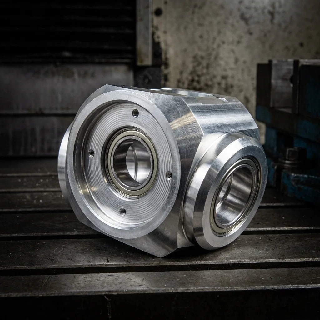
CNC machining tolerances for robot parts define the allowable deviation from a design's nominal dimensions, typically ranging from ±0.1 mm for structural links to H7 (+0.021/0 mm) for precision bearing bores in actuators. Achieving sub-micron accuracy in robotics is critical for zero-backlash motion, sensor alignment, and multi-DOF synchronization. Alloyer provides high-precision CNC services with integrated DFM feedback to optimize your robot’s performance-to-cost ratio.
Caption: A high-precision robot joint housing machined from 7075-T6 aluminum. Precision bearing bores like these require H7 tolerances to ensure smooth actuator rotation and long-term durability.Key Things to Know About Robotics Machining Tolerances
---
Why Tolerances Define Robot Performance
In robotics, a "loose" tolerance isn't just a fitment issue—it's a control system failure. A 0.05 mm gap in a gear housing can translate to several degrees of backlash at the end-effector of a 1-meter robotic arm.
Bores and Shafts (The H7 Standard)
Most robotic actuators rely on precision bearings. If the bore is too large, the bearing will spin within the housing, causing heat and vibration. If too small, the bearing is crushed, leading to premature failure. Alloyer maintains H7 tolerances for aluminum and titanium components using high-speed boring tools and thermal-compensated CNC centers.Concentricity and Gear Mesh
Cycloidal drives, common in humanoid robots, require input and output bores to be perfectly concentric (within 0.015 mm). Any deviation causes uneven load distribution on the pins or wave generator, leading to jerky motion and reduced torque capacity.Flatness for Mounting
Actuator face mounts must be flat within 0.02 mm to prevent "cocking" the motor. A tilted motor shaft introduces radial loads on the bearings that the system wasn't designed to handle, significantly shortening the robot's Mean Time Between Failures (MTBF).---
Precision Reference Table for Robotics Materials
| Material | Standard Linear Tolerance | High-Precision Bore (H7) | Surface Finish (Ra) | Thermal Stability | Machinability |
|---|---|---|---|---|---|
| Al 6061-T6 | ±0.05 mm | +0.021/0 mm | 0.8 µm | Excellent | Excellent |
| Al 7075-T6 | ±0.03 mm | +0.021/0 mm | 0.4 µm | Excellent | Good |
| Ti-6Al-4V | ±0.05 mm | +0.025/0 mm | 0.8 µm | Superior | Poor |
| PEEK | ±0.10 mm | +0.040/0 mm | 1.6 µm | Fair | Fair |
| Delrin (POM) | ±0.12 mm | +0.050/0 mm | 1.6 µm | Poor | Good |
| 17-4PH Steel | ±0.02 mm | +0.015/0 mm | 0.4 µm | Excellent | Fair |
---
CNC Machining Challenges for Tight-Tolerance Parts
1. Thin-Wall Vibration (Chatter)
Robotic components are often pocketed to save weight. If walls are thinner than 1.0 mm, the part will vibrate (chatter) during the final pass, making it impossible to hold a tolerance tighter than ±0.1 mm.2. Tool Deflection in Deep Pockets
When machining gearbox housings with deep internal features, long end mills can deflect. This causes "tapered" walls where the top of the pocket is wider than the bottom. Alloyer uses 5-axis setups to reduce tool stick-out and maintain verticality.3. Material Stress Relief
Materials like 7075-T6 aluminum can "move" after being released from the CNC fixtures due to internal stresses. For critical humanoid robot parts, we perform a roughing pass, followed by a secondary finishing pass after the material has stabilized.---
DFM Checklist for High-Precision Robot Parts
1. Standardize Your Tolerances Specify ±0.1 mm for 90% of the part and reserve tight ±0.02 mm tolerances only for bearing bores and mating faces. This reduces cost by 30%.
2. Avoid Sharp Internal Corners Ensure all internal corners have a radius larger than the radius of the smallest end mill (e.g., use a 3.5 mm radius for a 6 mm tool) to prevent tool chatter at the corners.
3. Thread Depth in Aluminum For M3 or M4 screws in 7075 aluminum, ensure the tapped hole is at least 2.5x the diameter in depth to handle the high vibration and dynamic torque of robot joints.
4. Hole-to-Edge Distance Keep holes at least 2x the diameter away from the edge of the part. Tight tolerances on holes near thin walls are difficult to maintain due to material deformation.
---
Cost Impact of Tolerance Selection
| Tolerance Level | Description | Machine Setup Complexity | Relative Cost | Application |
|---|---|---|---|---|
| ±0.25 mm | Rough/Structural | Low | 0.8x | Outer covers, heat sinks |
| ±0.10 mm | Standard CNC | Medium | 1.0x | Frame links, motor mounts |
| ±0.05 mm | High Precision | High | 1.5x | Actuator housings, sensor mounts |
| ±0.01 mm | Ultra Precision | Extreme | 3.0x+ | Bearing fits, gearbox internals |
Frequently Asked Questions
What is the most common tolerance for robot parts?
The most common tolerance is ±0.1 mm (0.004"). This is the standard "as-machined" tolerance for most CNC shops and is sufficient for 80% of robot components like structural arms, brackets, and enclosures.Why is H7 tolerance important for robot joints?
H7 is a specific "fit" tolerance that ensures a precision bearing sits securely in its housing without being loose enough to rattle or tight enough to deform the bearing race. In high-DOF systems like humanoid legs, H7 is the difference between a smooth walk and a jerky, unstable gait.How does material choice affect tolerance?
Metals like Aluminum 7075 are extremely stable and can hold ±0.01 mm consistently. Plastics like Delrin absorb moisture and expand with heat, making them unsuitable for anything tighter than ±0.1 mm over long production runs.Can Alloyer achieve ±0.005 mm tolerances?
Yes, but typically only for small features in hardened steels (17-4PH) or high-grade aluminum. Such tolerances require temperature-controlled environments and dedicated inspection tools. Contact our engineering team for a feasibility review.---
Explore more CNC machining guides on the Alloyer Blog.
---
---
Ready to machine your robotic components? Upload your CAD for an instant DFM review and precision tolerance check. 1-piece prototyping accepted. Get Quote →