
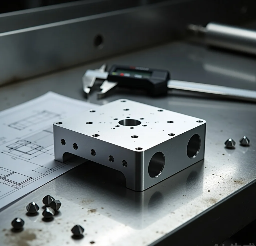
 A typical robotics bracket after first machining pass — notice the corner radii and through-holes designed for single-setup manufacturing.
Geometry traps — pockets, walls, holes, and engravings that look fine in CAD but break the budget in the shop
Tolerance strategy — when ±0.01mm is worth it and when it's just burning money
Process planning — how to avoid the "one more operation" death spiral
Post-processing gotchas — what anodizing actually does to your dimensions
1. Geometry and access
Most DFM failures start with geometry that looks perfectly reasonable on a screen but ignores the physical reality of a rotating end mill.
1.1 Deep pockets with sharp internal corners
We see this at least twice a week. A designer uploads a beautiful bracket with deep pockets for weight reduction — and every internal corner is exactly 90°.
The fix: add corner radii ≥1.5mm (0.0625″). This lets the tool flow through the corner without fighting itself.
1.2 Features a standard tool can't reach
Internal O-ring grooves, T-slots, or undercuts require special tooling. Rule of thumb: if you can't insert a straight tool from the closest accessible face, redesign it.
1.3 Walls thinner than 1mm in aluminum
Aluminum walls under 1mm act like tuning forks under cutting forces, causing vibration and poor finish.
| Material | Absolute minimum | Recommended |
|---|---|---|
| Aluminum 6061/7075 | 0.8mm | ≥1.5mm |
| Stainless 303/316 | 1.0mm | ≥1.5mm |
| Titanium Ti-6Al-4V | 1.2mm | ≥2.0mm |
| PEEK | 1.5mm | ≥2.5mm |
1.4 Blind holes deeper than 6× diameter
Thread engagement beyond 1.5–2× the nominal diameter adds almost nothing to joint strength. Specifying 40mm depth for an M8 hole only adds cost.
1.5 Text and logos engraved too deep
Keep engraving depth to 0.2–0.3mm. Logos at 0.5mm depth can add $20–40 to a prototype part due to cycle time.
2. Tolerance strategy
Applying tight tolerances (±0.01mm) everywhere is a budget killer. Apply them surgically.
| Feature type | Recommended tolerance | When to go tighter |
|---|---|---|
| Housing walls | ISO 2768-m | Basically never |
| Press-fit bores | H7 (+0.015/0mm) | Always |
| Slip-fit shafts | g6 (−0.012/−0.004mm) | Always |
| Mounting holes | ±0.1mm | Most cases |
3. Process planning
Every additional operation (setup) is a multiplier on cost and lead time. Design for single-setup machining when possible.
4. Post-processing
Type III hard anodizing adds 25–75μm of coating per side. A Ø10.000mm bore can shrink to Ø9.850mm after coating.
5. Printable DFM checklist
Frequently asked questions
Q: What's the most expensive DFM mistake in robotics?
A: Over-tolerancing. Calling out tight bands everywhere can triple a quote with zero benefit.
Q: Does anodizing change part dimensions enough to worry about?
A: Type II (standard) usually not. Type III (hardcoat) absolutely yes — account for 25–75μm per side.