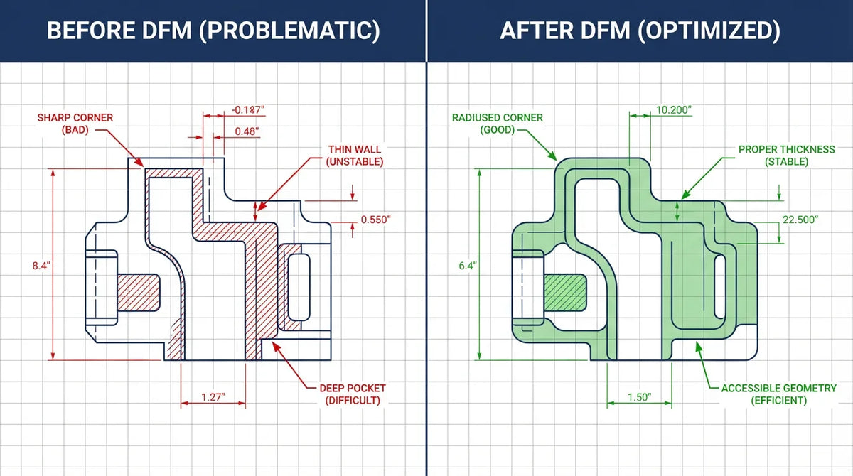
Every rejected quote, delayed delivery, or scrapped part starts with a design that could have been optimized earlier. This checklist distills 10,000+ Alloyer projects into 12 actionable DFM steps — from file export to final tolerance callouts.

How to Use This Checklist
Print this page or bookmark it. Run through all 12 steps before uploading your CAD files. Each section includes:
- The rule — what to check
- Why it matters — cost or lead time impact
- Quick fix — how to correct common mistakes
- Alloyer standard — our default capability threshold
Step 1: File Format & Integrity
Common Mistake: Uploading STL files for CNC quotes. STL is for 3D printing. CNC requires STEP or IGES with precise NURBS surfaces.
| Format | Use For | Alloyer Accepts |
|---|---|---|
| STEP (.stp/.step) | CNC machining, sheet metal | Preferred |
| IGES (.igs/.iges) | Legacy CAD compatibility | Accepted |
| STL (.stl) | 3D printing only | Not for CNC |
| OBJ/FBX | Visualization, animation | Not accepted |
Step 2: Wall Thickness

| Material | Minimum Wall | Recommended | Risk if Violated |
|---|---|---|---|
| Aluminum 6061/7075 | 0.5mm | ≥ 1.0mm | Vibration, chatter, deformation |
| Stainless 303/304/316L | 0.8mm | ≥ 1.5mm | Tool deflection, poor finish |
| Titanium Grade 5 | 1.0mm | ≥ 2.0mm | Heat buildup, work hardening |
| PEEK / Plastics | 1.0mm | ≥ 1.5mm | Melting, warping |
Step 3: Internal Corner Radii

Design Tip: Corner radius should be 1.5–2× your end mill radius. For a standard 3mm end mill, use 1.5–2mm internal radius. This reduces stress concentration and allows proper tool engagement.
Step 4: Tool Access & Undercuts

| Feature Type | Standard Access | Requires Special Tool |
|---|---|---|
| Through-holes | Top/bottom access OK | — |
| Blind holes | Top access only | Bottom entry requires flip |
| Side holes | Perpendicular to axis | Angled holes need 4th/5th axis |
| Undercuts | Not machinable with standard tools | T-slot cutter, special setup |
| Internal threads | Through-hole preferred | Blind hole needs thread relief |
Step 5: Pocket Depth & Aspect Ratio
Cost Impact: Pockets with depth > 4× width require extended reach tools, slower feeds, and often multiple depth passes. This can add 30–50% to machining time.
Step 6: Hole Specifications
| Hole Type | Standard | Custom Cost Adder |
|---|---|---|
| Through hole | Standard drill | None |
| Blind hole | Standard drill + depth | +10–15% |
| Tapped hole (cutting tap) | M2–M12 standard | None |
| Tapped hole (forming tap) | Requires ductile material | +5% |
| Threaded insert | Helicoil, PEM | Hardware + labor |
| Reamed hole (tight tolerance) | H7, H8 tolerance | +20% (extra op) |
Step 7: Tolerance Review
Cost Insight: Each tight tolerance adds inspection time and may require slower machining or grinding. A part with ±0.01mm tolerance can cost 2–3× more than the same part at ±0.1mm.
| Tolerance Class | Typical Range | Cost Impact |
|---|---|---|
| Standard (as-machined) | ±0.125mm | Baseline |
| Precision | ±0.05mm | +15–25% |
| High precision | ±0.025mm | +30–50% |
| Ultra precision | ±0.01mm or better | +100–200% |
Step 8: Surface Finish Requirements
Step 9: Part Orientation & Setup
Setup Cost: Each additional setup (part flip or rotation) adds programming time, fixture cost, and alignment risk. A 1-setup part is always cheaper than a 3-setup part.
Step 10: Material Selection
| Material | Relative Cost | Best For |
|---|---|---|
| Aluminum 6061-T6 | 1.0× (baseline) | General purpose, anodizing |
| Aluminum 7075-T6 | 1.3× | High strength, aerospace |
| Stainless 303 | 1.5× | Free-machining, corrosion resistance |
| Stainless 316L | 1.8× | Medical, marine, food grade |
| Titanium Grade 5 | 4–5× | High strength-to-weight, bio |
| PEEK | 6–8× | High temp, chemical resistance |
Step 11: Thread & Hardware
Step 12: Text & Engraving
Quick Reference: DFM Violation Cost Impact
| Violation | Typical Cost Adder | Lead Time Impact |
|---|---|---|
| Sharp internal corners | +10–20% | +1–2 days |
| Thin walls (<0.8mm) | +20–40% | +2–3 days |
| Deep pockets (>4× width) | +30–50% | +1–2 days |
| Undercuts | +50–100% | +3–5 days |
| Tight tolerances (±0.01mm) | +100–200% | +2–4 days |
| Extra setups (>2) | +25–50% per setup | +1–2 days per setup |
| Non-standard hole sizes | +15–25% | +1 day |
Downloadable PDF Checklist
Want a printable version? Contact our engineering team and we'll send you a PDF version of this checklist formatted for your shop clipboard.
Next Steps
- Run this checklist on your next design before exporting
- Upload your optimized file to Alloyer's instant quote tool
- Review our DFM feedback — we flag remaining issues within 4 hours
- Iterate if needed — faster to fix in CAD than on the machine
Engineering Support: Every Alloyer quote includes free DFM review. Upload your files and our manufacturing engineers will flag any remaining issues before production starts.