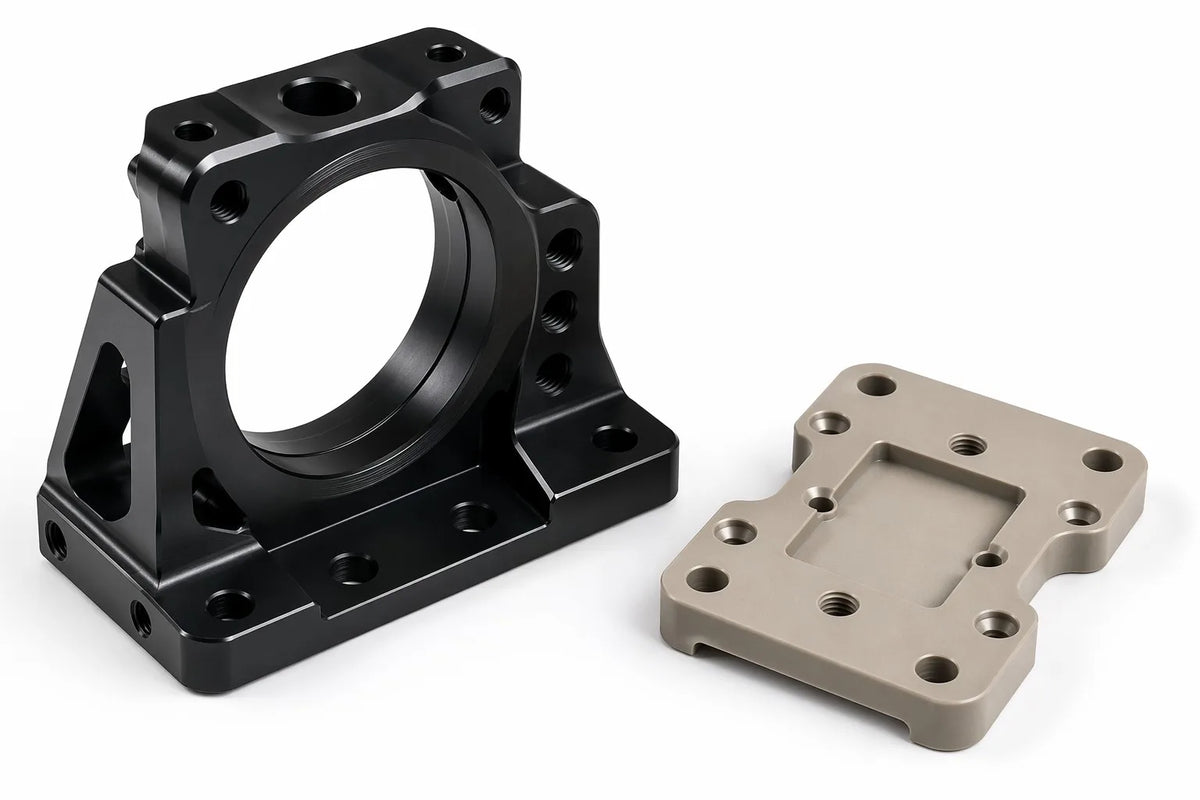
CNC machining for robot sensor mounts demands a careful balance of stiffness for positional accuracy, vibration isolation for signal cleanliness, and thermal stability for consistent calibration. Aluminum 6061-T6 is the default for general-purpose brackets (lowest cost, excellent machinability), while PEEK excels when electrical isolation is critical, and carbon fiber wins for drone and lightweight platforms where every gram matters. Alloyer machines all five materials with 72-hour prototyping, helping you select the right sensor mount material for your specific sensor suite.

Key Things to Know
- Stiffness Drives Sensor Accuracy: A LiDAR or stereo camera mount that deflects 0.01 mm under vibration translates to a 10 mm position error at 10 m range. Materials with elastic moduli above 68 GPa (6061-T6 and above) are mandatory for long-range perception sensors.
- Electrical Isolation Is a Hard Requirement for IMUs: Inertial Measurement Units are sensitive to ground-loop noise. Mounting them on PEEK or FR4/G10 insulators breaks the conductive path between the sensor PCB and the robot chassis, reducing IMU noise floor by up to 40%.
- Thermal Expansion Mismatch Can Uncalibrate Sensors: An aluminum bracket (CTE ≈ 23.6 × 10⁻⁶/°C) bolted to a steel sensor housing (CTE ≈ 10.8 × 10⁻⁶/°C) will shift the sensor's optical axis by ~0.013 mm per °C per 100 mm of span. This shift is cumulative — on a 50°C temperature swing across a 200 mm stereo baseline, the calibration error exceeds pixel-level accuracy.
- Vibration Damping, Not Just Stiffness, Matters for Cameras: A perfectly stiff mount transmits motor vibration directly to the camera sensor, producing rolling-shutter artifacts. POM (Delrin) bushings or isolator pads machined into the mount design can reduce transmitted vibration amplitude by 60–80% at frequencies above 100 Hz.
- Multi-Sensor Pods Need Single-Setup Machining: When a single bracket mounts a LiDAR, two cameras, and an IMU, the relative position of every sensor interface must be held within ±0.02 mm true position. Alloyer machines these multi-sensor pods in one 5-axis setup, ensuring all sensor bores share the same coordinate reference.
Al 6061-T6: The General-Purpose Workhorse
Properties
Density: 2.70 g/cm³ | Yield Strength: 276 MPa | Elastic Modulus: 68.9 GPa | CTE: 23.6 × 10⁻⁶/°C (ASTM B308/B308M).
Best For
LiDAR turret bases, stereo camera bars, general-purpose sensor brackets, encoder mounts, and any application where cost per mount must stay under $30.
CNC Considerations
Excellent machinability. Standard carbide tooling at 10,000–18,000 RPM. Achieves Ra 1.6 μm as-machined. Type II anodizing (matte black) is recommended for all optical sensor mounts — the dark, non-reflective surface prevents stray IR reflections that confuse depth cameras and LiDAR sensors. Lead time: 3–5 days.Cost
1.0x baseline. Raw material ~$4–6/kg. A typical LiDAR mount bracket (100 × 60 × 15 mm) costs $18–35 (1 pc).
Al 7075-T6: High-Stiffness Precision
Properties
Density: 2.81 g/cm³ | Yield Strength: 503 MPa | Elastic Modulus: 71.7 GPa | CTE: 23.6 × 10⁻⁶/°C (ASTM B211).
Best For
Long-baseline stereo camera bars (>300 mm span), high-G sensor mounts for legged robots, anti-vibration platforms for laser scanners, and any bracket where sub-0.005 mm deflection under 10G acceleration is required.
CNC Considerations
Good machinability — 15–20% slower feeds than 6061-T6. Recommended: 8,000–14,000 RPM. Hardcoat anodizing (Type III) adds 2–3 days to lead time and provides a wear-resistant surface for the mounting bolts that are frequently torqued during sensor calibration and swap-outs. Lead time: 5–7 days.Cost
1.5x vs 6061-T6. A typical long-baseline stereo bar (300 × 40 × 15 mm) costs $40–70 (1 pc).
PEEK: Electrical Isolation Specialist
Properties
Density: 1.30 g/cm³ | Yield Strength: 90–100 MPa | Elastic Modulus: 3.6 GPa | Volume Resistivity: 10¹⁶ Ω·cm (ASTM D638).
Best For
IMU isolator plates, electrical isolation spacers between sensor PCBs and aluminum chassis, non-magnetic sensor mounts for magnetometer-equipped drones, and high-temperature sensor brackets (continuous service to 250°C).
CNC Considerations
Fair machinability — stress-relief annealing required before finish passes. Recommended: 6,000–10,000 RPM with compressed air cooling. Achieves Ra 0.8 μm with proper feeds. PEEK's high dielectric strength (19 kV/mm) makes it the gold standard for breaking ground loops — an essential feature when mounting sensitive analog sensors to a robot chassis that shares a ground plane with high-current motor drivers. Lead time: 5–7 days.Cost
15.0x vs 6061-T6. A typical IMU isolator plate (40 × 40 × 5 mm) costs $60–120 (1 pc). Cost is dominated by material price ($80–150/kg).
FR4/G10: Budget Insulator
Properties
Density: 1.85 g/cm³ | Flexural Strength: 340 MPa (warp direction) | Elastic Modulus: 24 GPa (warp) | Volume Resistivity: 10¹² Ω·cm (NEMA LI-1).
Best For
Budget electrical isolation plates, sensor PCB mounting boards, drone power distribution mounts, and sensor spacers where the cost of PEEK is not justified but electrical isolation is still required.
CNC Considerations
Fair machinability — glass-fiber reinforcement is highly abrasive. Carbide tooling with TiAlN coating is mandatory; tool life is approximately 1/3 of aluminum. Dry machining only — coolant causes FR4 to absorb moisture and swell, compromising dimensional stability. The machined edges will show visible glass-fiber texture — this does not affect performance but is a cosmetic consideration. Lead time: 5–7 days.Cost
1.2x vs 6061-T6. A typical sensor PCB mount plate (80 × 50 × 3 mm) costs $15–25 (1 pc).
Carbon Fiber (CFRP): Ultimate Stiffness-to-Weight
Properties
Density: 1.55 g/cm³ | Tensile Strength: 600–800 MPa | Elastic Modulus: 70 GPa (tensile, fiber direction) | CTE: ~0–2 × 10⁻⁶/°C (ASTM D3039).
Best For
Drone LiDAR mounts, lightweight stereo camera bars, gimbal sensor platforms, and any application where weight and near-zero thermal expansion are simultaneously required.
CNC Considerations
Special machinability — diamond-coated tooling required. Dry machining with HEPA dust extraction. The near-zero CTE of carbon fiber (0–2 × 10⁻⁶/°C) is its standout feature for sensor mounts: a 300 mm carbon fiber stereo bar expands less than 0.003 mm over a 50°C temperature swing, versus 0.35 mm for 6061-T6 aluminum. This means the extrinsic calibration (the transform between camera coordinate frames) remains valid across the robot's entire operating temperature range. Lead time: 7–12 days.Cost
12.0x vs 6061-T6. A typical drone LiDAR mount (100 × 60 × 3 mm plate) costs $90–180 (1 pc).
Material Comparison Table
| Material | Elastic Modulus (GPa) | CTE (×10⁻⁶/°C) | Electrical Isolation | Machinability | Cost Index* | Best For |
|---|---|---|---|---|---|---|
| Al 6061-T6 | 68.9 | 23.6 | No (Conductive) | Excellent | 1.0x | General brackets, LiDAR bases, encoder mounts |
| Al 7075-T6 | 71.7 | 23.6 | No (Conductive) | Good | 1.5x | Long-baseline stereo bars, high-G mounts |
| PEEK | 3.6 | 47 | Excellent (10¹⁶ Ω·cm) | Fair | 15.0x | IMU isolators, high-temp sensor mounts |
| FR4/G10 | 24 | 14 | Good (10¹² Ω·cm) | Fair (Abrasive) | 1.2x | Budget isolation plates, PCB mounts |
| Carbon Fiber | 70 (tensile) | 0–2 | No (Conductive) | Special | 12.0x | Drone sensor platforms, thermally stable bars |
DFM Tips for Sensor Mounts
1. Design Isostatic Mounting to Avoid Over-Constraining the Sensor
A sensor bolted to a flat plate with four bolts is over-constrained — any slight non-planarity in the bracket or sensor housing introduces bending stress that shifts the optical axis. Use a three-point kinematic mount: one conical seat for position, one V-groove for rotation constraint, and one flat pad for the third point. Alloyer can CNC-machine all three features in a single setup to ±0.01 mm accuracy.
2. Include Thermal Relief Slots for Long-Baseline Mounts
For stereo bars longer than 200 mm, machine 2 mm wide × 20 mm long slots perpendicular to the bar axis at the midpoint between sensor mounting interfaces. These slots act as thermal expansion joints, absorbing the CTE-driven length change locally rather than allowing it to accumulate at the sensor mounting point. This simple feature reduces the effective thermal displacement at the sensor by 60–70%.
3. Specify Countersunk Holes with Controlled Depth for Optical Sensors
LiDAR and depth camera mounting bolts must sit flush or below the sensor's mounting face — a protruding bolt head creates an occlusion in the sensor's field of view. Specify countersunk holes with a depth tolerance of +0/-0.1 mm relative to the bolt head thickness. Alloyer uses depth-controlled spot-facing cycles to achieve this consistently.
4. Use PEEK or FR4 Washers as Electrical Break Points
Rather than machining the entire sensor bracket from expensive PEEK, design the bracket in 6061-T6 aluminum with recessed pockets that accept PEEK or FR4 washer inserts at each bolt location. This creates an electrical break between the sensor housing and the chassis at every fastener, achieving the isolation benefit of a full-PEEK mount at roughly 15–20% of the cost. The washers are machined as separate small-diameter parts and pressed or bonded into the bracket.
5. Add a Dowel-Pin Datum Hole for Recalibration Reference
Machine one H7 dowel-pin hole (position ±0.01 mm) on every sensor bracket, located in a non-critical area of the bracket. During initial calibration, insert a tooling ball into this hole and record its position relative to the robot's base frame. After any sensor swap or bracket replacement, the tooling ball provides a known reference point for rapid recalibration without repeating the full extrinsic calibration procedure.
FAQ
Q: Do I really need PEEK for an IMU mount, or is 3D-printed PLA good enough?
3D-printed PLA provides some electrical isolation but has 10× lower stiffness than PEEK (E ≈ 0.35 GPa vs 3.6 GPa). This softness allows the IMU to vibrate relative to the chassis, introducing low-frequency noise into the accelerometer and gyroscope signals. A CNC-machined PEEK IMU mount costs $60–120 and eliminates this noise source — for a robot whose state estimation depends on IMU data, this is one of the highest-ROI component upgrades available.
Q: How do I eliminate rolling-shutter artifacts in my stereo camera caused by motor vibration?
Replace the rigid aluminum camera mounts with a design that incorporates POM (Delrin) vibration-isolating bushings at the bolt interfaces. The POM bushings (machined as press-fit inserts into the aluminum bracket) reduce transmitted vibration by 60–80% at frequencies above 100 Hz — the range where rolling-shutter artifacts become visible. Alloyer can machine both the bracket and the POM bushings in a single order.
Q: Why does my LiDAR calibration drift after the robot warms up?
This is almost certainly thermal expansion of the aluminum LiDAR mount. A 6061-T6 bracket expands ~0.013 mm per °C per 100 mm of span. Over a 40°C warm-up (from 20°C ambient to 60°C near the robot's motors), a 150 mm bracket grows by ~0.08 mm — enough to shift the LiDAR's point cloud by 8 mm at 10 m range. Solution: switch the bracket to carbon fiber (CTE ~1 × 10⁻⁶/°C), which expands only 0.006 mm over the same temperature swing.
Q: Can you machine a multi-sensor pod with integrated cable routing channels?
Yes. Alloyer machines multi-sensor pods in a single 5-axis setup, holding all sensor interface bores to ±0.02 mm true position. We can integrate cable-routing channels (3–5 mm wide, 2–3 mm deep) directly into the bracket geometry, eliminating the need for zip ties or external cable management that adds bulk and can snag during robot operation.
More from Alloyer Blog
Need precision sensor mounts for your robot?
Upload your CAD to Alloyer's AI engine for an instant quote with free DFM review. All five materials in stock — from standard 6061-T6 brackets to carbon fiber thermal-stable platforms. 1-piece prototyping accepted, 72-hour delivery.
Upload CAD & Get Quote →