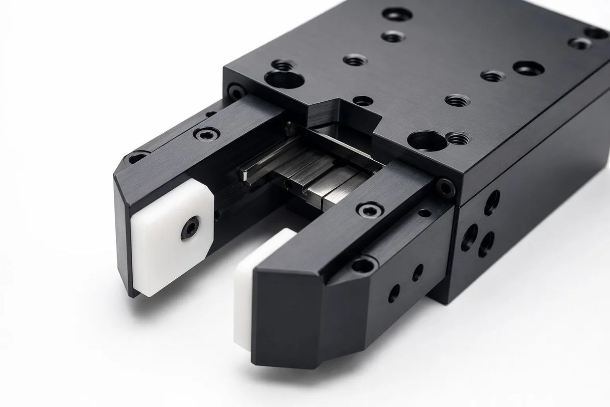
CNC machining for robotic end-effectors and grippers is the precision manufacturing process of producing parallel jaw grippers, vacuum end-effector plates, soft robotic gripper molds, and specialized tool changers for industrial, collaborative, and research robot arms. Gripper components demand a unique combination of high stiffness for precise gripping force control, low mass to maximize payload, and surface finishes tailored for friction or release. Alloyer specializes in 5-axis gripper machining with 72-hour prototyping, supporting everything from hardened 7075-T6 aluminum jaws to self-lubricating POM fingertips.

Key Things to Know About CNC Machining for Robotic Grippers
- Material Pairing Is Critical: Gripper jaws must be stiff (7075-T6 aluminum) while fingertip inserts benefit from compliance and friction — POM (Delrin) or carbon-fiber-filled Nylon provide the ideal balance of grip and wear resistance without marring the workpiece.
- Rail and Guide Precision Dictates Grip Repeatability: Parallel jaw grippers rely on linear guide rails machined to ±0.01 mm parallelism over their full stroke. A 0.02 mm deviation in rail alignment translates to inconsistent grip force across the jaw opening — unacceptable for fragile object handling.
- Weight at the End of the Arm Is Multiplied: Every gram saved in the gripper reduces the torque demand on the robot's wrist joint by a factor of its reach. CNC pocketing can remove up to 60% of a gripper body's mass while maintaining structural stiffness within 5% of the solid design.
- Surface Texture Controls Grip, Not Just Aesthetics: A gripper fingertip machined to Ra 3.2 μm with a cross-hatch pattern provides significantly more friction than a polished Ra 0.8 μm surface. Alloyer can apply controlled surface textures directly during the CNC process — no secondary treatment required for most grip applications.
- Quick-Change Interfaces Need Zero-Play Locking: Tool changer plates must mate with the robot wrist and the gripper within ±0.01 mm flatness to eliminate any wobble at the tool interface. A single-setup 5-axis machining strategy ensures both sides of the quick-change coupler are perfectly co-planar.
Why Robotic Grippers Demand Specialized CNC Machining
A robotic gripper is the only part of the robot that physically touches the workpiece — it's where the entire automation investment either succeeds or fails at the point of contact. Unlike structural chassis parts that only bear loads, gripper components must simultaneously manage precise kinematics, controlled friction, and rapid wear over millions of cycles.
Stiffness-to-Weight: The Defining Trade-Off
Every gram of gripper mass sits at the farthest point from the robot's base, where it exerts maximum leverage against the wrist motors. A gripper that weighs 500 g on a robot with a 500 mm reach effectively adds 2.5 N·m of static torque to the wrist joint — equivalent to derating the robot's payload by roughly 250 g. CNC machining from 7075-T6 aluminum allows the gripper body to be pocketed down to 1.5 mm wall thickness in non-load-bearing regions, achieving a 60% mass reduction while maintaining >95% of the solid body's bending stiffness. This is impossible with cast or 3D-printed grippers, which require thicker walls for process reliability.
Kinematic Precision in Compact Envelopes
A parallel jaw gripper typically operates within an envelope of 80 × 40 × 30 mm — roughly the size of a matchbox. Inside this volume, it must house two linear guide rails, a leadscrew or pneumatic piston, two jaw carriages, and up to four bearing bushings. CNC machining achieves the required bore-to-bore parallelism of ±0.01 mm because all guide bores are machined in a single 5-axis setup from the same datum. Multi-setup machining or 3D printing introduces cumulative alignment errors that manifest as jaw racking — one side of the jaw closing before the other, reducing grip reliability.
Custom Fingertip Geometries for Application-Specific Grip
Gripper fingertips are where the generic gripper becomes a custom tool. A fingertip designed to pick a cylindrical object needs a V-groove with a 120° included angle and a root radius that matches the object. A fingertip for flat sheet metal needs a planar contact pad with a cross-hatch surface texture. CNC machining produces these custom geometries directly in POM, carbon-fiber-filled Nylon, or hard-anodized 7075-T6 — with a single fingertip taking 1–3 hours to machine and ship-ready in 72 hours.
Material Properties for Robotic Gripper Components
| Material | Density (g/cm³) | Yield Strength (MPa) | Friction (vs Steel) | Machinability | Cost Index* | Gripper Application |
|---|---|---|---|---|---|---|
| Al 7075-T6 | 2.81 | 503 | 0.4–0.6 | Good | 1.5x | Gripper bodies, jaw carriages, rail guides |
| POM (Delrin) | 1.41 | 65 | 0.2–0.35 | Excellent | 0.8x | Fingertip inserts, soft-contact pads, bushings |
| Carbon-Fiber Nylon | 1.25 | 90 | 0.3–0.45 | Good | 0.9x | High-grip fingertips, wear-resistant jaws |
| Al 6061-T6 | 2.70 | 276 | 0.4–0.6 | Excellent | 1.0x | Vacuum plates, mounting flanges, covers |
| 17-4PH Stainless | 7.80 | 1,170 | 0.5–0.8 | Fair | 3.5x | High-cycle jaw pins, tool changer locks |
Critical Components: CNC Requirements
1. Parallel Jaw Gripper Body
Function: The main structural housing that contains the linear guide rails, actuation mechanism (pneumatic piston or leadscrew), and jaw carriage slides. Material: Al 7075-T6 (high-stiffness) or Al 6061-T6 (budget prototypes). Tolerance: Guide rail bores parallelism ±0.01 mm over full stroke; jaw carriage slide surfaces flatness 0.01 mm. Surface Finish: Ra 0.8 μm on guide rail bores; Ra 1.6 μm + Type III hardcoat on sliding surfaces. CNC Challenges: The gripper body is a deep, narrow pocket — typically 80 mm long, 30 mm wide, and 40 mm deep — requiring long-reach tooling with a length-to-diameter ratio of up to 6:1. Alloyer uses vibration-dampened extended toolholders and trochoidal milling paths to maintain ±0.01 mm accuracy at the bottom of the pocket, where tool deflection is highest.2. Custom Interchangeable Fingertips
Function: The part-specific contact interface that grips the workpiece. Fingertips are typically bolted to the jaw carriage and swapped when the robot changes tasks. Material: POM (Delrin) for general-purpose grip, carbon-fiber-filled Nylon for abrasive workpieces, or 7075-T6 for high-temperature environments (>100°C). Tolerance: Mounting hole pattern ±0.02 mm true position; grip face profile ±0.05 mm. Surface Finish: Ra 3.2 μm with a controlled cross-hatch pattern for grip; Ra 0.8 μm polished for release applications. CNC Challenges: Fingertips are produced in matched pairs — the left and right fingertips must be mirror images within ±0.02 mm to ensure symmetrical grip force. Alloyer machines both fingertips in a single fixture, flipping the CAM program to produce the mirror geometry from the same tool offsets, guaranteeing dimensional symmetry.3. Vacuum End-Effector Plate
Function: A flat or contoured plate with an integrated vacuum channel network and suction cup mounting points, used for pick-and-place of flat objects (sheet metal, glass, PCBs). Material: Al 6061-T6 (cost-optimized) or carbon-fiber-filled Nylon (ESD-safe for electronics). Tolerance: Vacuum channel depth ±0.05 mm; mounting face flatness 0.03 mm; suction cup port positions ±0.05 mm. Surface Finish: Ra 1.6 μm on sealing surfaces for reliable vacuum; Type II anodize for corrosion resistance in humid environments. CNC Challenges: Vacuum channels are shallow (1–2 mm deep) serpentine grooves that must maintain consistent cross-sectional area to ensure even vacuum distribution. Alloyer uses ball-end mills with a constant-stepover finishing pass to produce smooth channel floors free of tool marks that would create vacuum leaks.Tolerances & Surface Finishes for Gripper Components
| Feature | Specified Tolerance | Required Surface Finish | Gripper Performance Impact |
|---|---|---|---|
| Guide Rail Bore | H7 (+0.015/0 mm) | Ra 0.8 μm | Ensures friction-free jaw motion over millions of cycles |
| Jaw Slide Surface | Flatness 0.01 mm | Ra 0.8 μm + Hardcoat | Prevents jaw racking and uneven grip force |
| Fingertip Mounting Pattern | ±0.02 mm true position | Ra 3.2 μm | Enables hot-swapping fingertips without recalibration |
| Vacuum Channel Floor | Depth ±0.05 mm | Ra 1.6 μm | Eliminates vacuum leaks from tool-mark channels |
DFM Tips for Robotic Gripper Parts
1. Design the Jaw Interface for Interchangeability
Standardize the fingertip-to-jaw mounting pattern across all your gripper sizes — for example, use M3 bolts on a 15 × 15 mm bolt pattern for small grippers and M4 on a 20 × 20 mm pattern for medium grippers. This allows a single set of custom fingertips to work across multiple gripper models, reducing the total number of unique CNC parts by up to 50%.
2. Incorporate Lightweighting Pockets Early in the Design
Gripper bodies are prime candidates for topology optimization. Design rectangular or kidney-shaped pockets in non-load-bearing regions with a minimum wall thickness of 1.5 mm and a minimum pocket-to-edge distance of 3 mm. Avoid pockets that intersect with guide rail bores — maintain at least 2× the bore diameter as solid material around each bore.
3. Specify the Grip Surface Texture Explicitly on the Drawing
Do not leave grip surface finish to the machinist's default. Specify "Ra 3.2 μm, cross-hatch pattern, 0.05 mm stepover" for grip surfaces and "Ra 0.8 μm, polished" for release surfaces directly in the CAD notes. Alloyer's CAM programmer will apply the specified texture as part of the finishing toolpath — no secondary process required.
4. Use POM Inserts to Protect Both the Workpiece and the Gripper
In applications where the workpiece surface finish is critical (e.g., polished aluminum, coated glass, injection-molded parts), design the metal jaw body with a dovetail slot to accept a replaceable POM fingertip insert. The POM insert wears sacrificially — replace it after ~50,000 cycles at a cost of $5–10 per insert, versus replacing the entire machined jaw at $80–150.
5. Add Alignment Pins to the Tool Changer Interface
Quick-change tool changer plates should include two precision-ground alignment pins (H7/g6 fit) in addition to the locking mechanism. The pins carry the shear load and maintain ±0.005 mm repeatability; the locking mechanism only provides the clamping force. Without alignment pins, the locking mechanism alone typically drifts 0.02–0.05 mm after 10,000 tool changes.
Cost & Lead Time Reference
| Material | Typical Lead Time | Relative Cost | Min Qty | Recommended Use |
|---|---|---|---|---|
| Al 6061-T6 | 3-5 days | 1.0x | 1 pc | |
| Al 7075-T6 | 5-7 days | 1.5x | 1 pc | |
| POM (Delrin) | 3-5 days | 0.8x | 1 pc | |
| CF-Nylon | 5-7 days | 0.9x | 1 pc | |
| 17-4PH | 5-7 days | 3.5x | 1 pc |
Frequently Asked Questions
Q: How do I choose between a parallel jaw gripper and a custom vacuum end-effector?
Use a parallel jaw gripper when you need to handle objects with a defined geometry (cylinders, blocks) and require programmable grip force. Use a vacuum end-effector when handling flat, non-porous objects (sheet metal, glass, PCBs) at high speed, or when the object's surface is not accessible from the sides. Alloyer machines both types from the same material palette — some customers prototype both designs simultaneously and test grip reliability before committing to production.
Q: What grip force can a CNC-machined 7075-T6 gripper body withstand?
A typical CNC-machined 7075-T6 parallel jaw gripper body (80 × 40 × 30 mm envelope, 1.5 mm minimum wall) can safely transmit 200–400 N of grip force at the fingertips. The limiting factor is usually not the body itself but the actuation mechanism — pneumatic pistons above 10 bar or leadscrews above M8 may strip the aluminum mounting threads. Alloyer recommends Helicoil inserts for any threaded hole that sees >50 N of axial load.
Q: Can you machine the soft gripper molds used for silicone casting?
Yes. We machine mold cavities from Al 6061-T6 with Ra 0.4 μm polished surfaces for clean silicone release. Multi-part molds with alignment pins ensure the cast gripper fingers are dimensionally accurate to ±0.1 mm. Typical lead time for a single-cavity mold (100 × 50 × 30 mm) is 5–7 days.
Q: How many cycles can a CNC-machined POM fingertip last before replacement?
In typical pick-and-place duty (<50 N grip force, ambient temperature, clean workpieces), a POM fingertip lasts 30,000–50,000 cycles before grip performance degrades measurably. For abrasive workpieces or high-temperature environments, upgrade to carbon-fiber-filled Nylon for 80,000–120,000 cycle life, or to hardcoat-anodized 7075-T6 for essentially unlimited life at the cost of potential workpiece marring.
Q: Does Alloyer offer assembly and testing of complete gripper units?
We do not assemble complete grippers in-house — our scope is precision CNC machining of the individual components per your CAD. However, we machine all components for a single gripper in a coordinated batch with matched tool offsets and fixture datums, ensuring the parts assemble without interference. We recommend sourcing standard components (bearings, seals, pistons, fasteners) from industrial suppliers and performing final assembly and testing in your own facility.
More from Alloyer Blog
Need custom gripper components fast?
Upload your CAD to Alloyer's AI engine for an instant quote with free DFM review. Gripper parts in 7075-T6, POM, and carbon-fiber Nylon — 1-piece prototyping accepted with 72-hour delivery.
Upload CAD & Get Quote →