Robot gearbox housing machining is the high-precision CNC process of creating the protective and structural enclosure for robotic gear systems, such as harmonic drives, cycloidal drives, and planetary reducers. These housings must provide extreme torsional rigidity and maintain micron-level concentricity to ensure efficient torque transmission and zero-backlash motion. Alloyer specializes in machining gearbox housings from 7075-T6 aluminum and 17-4PH steel with H7 tolerances and 72-hour prototyping.
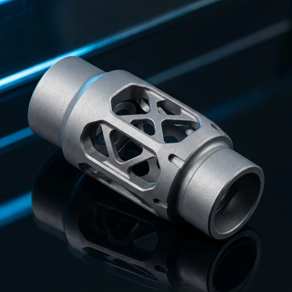
!Alloyer CNC machined aluminum 7075 robotic planetary gearbox housing with high-precision bores Caption: A high-precision planetary gearbox housing machined from 7075-T6 aluminum. Critical bearing bores are held to H7 tolerances to ensure smooth gear rotation and long-term reliability in humanoid robot actuators.
Key Things to Know About Gearbox Housing Machining
---
Material Selection for Robotic Gearbox Housings
Selecting the right material for a gearbox housing involves balancing weight, stiffness, and thermal properties. In high-DOF systems like humanoid legs, weight is the primary driver, while in industrial manipulators, stiffness and cost take priority.
Material Property Comparison Table
| Property | Al 6061-T6 | Al 7075-T6 | 17-4PH Steel | PEEK (GF30) | Winner (Robotics) |
|---|---|---|---|---|---|
| Density (g/cm³) | 2.70 | 2.81 | 7.80 | 1.50 | PEEK |
| Yield Strength (MPa) | 276 | 503 | 1170 | 160 | 17-4PH |
| Elastic Modulus (GPa) | 68.9 | 71.7 | 196 | 12 | 17-4PH |
| Thermal Cond. (W/m·K) | 167 | 130 | 17.9 | 0.25 | Al 6061 |
| Machinability | Excellent | Good | Fair | Fair | Al 6061 |
| Cost Index | 1.0x | 1.5x | 3.5x | 18.0x | Al 6061 |
Why 7075-T6 is the Humanoid Standard
For humanoid robot actuators, Aluminum 7075-T6 is the industry favorite. It provides nearly double the yield strength of 6061-T6, allowing for thinner walls and a lighter overall actuator assembly without sacrificing the rigidity needed for high-ratio gear reductions.---
Critical Manufacturing Challenges & Solutions
Machining gearbox housings for robotics introduces several technical hurdles that standard CNC shops often struggle with.
1. Maintaining Concentricity and Runout
In cycloidal drives, the "ring" of the housing must be perfectly concentric with the central bore. The Alloyer Solution: We perform "single-setup" machining where possible, using 5-axis centers to machine all critical bores in one operation. This eliminates the "stack-up" error associated with flipping parts between fixtures.2. Thin-Wall Vibration (Chatter)
To save weight, engineers often design housings with wall thicknesses below 1.5 mm. During machining, these walls can vibrate, causing poor surface finish and dimensional inaccuracy. The Alloyer Solution: We use custom vibration-dampening fixtures and specialized high-helix end mills to reduce radial cutting forces.3. Thermal Compensation
Titanium and Steel housings can expand significantly during long machining cycles. The Alloyer Solution: Our CNC centers utilize real-time thermal compensation probes to adjust tool offsets as the machine and workpiece temperature fluctuate, ensuring ±0.01 mm repeatability.---
DFM Checklist for Robotic Gearbox Housings
1. Standardize Bearing Bores Design bores to match standard metric bearing sizes (e.g., 22 mm, 26 mm). This allows us to use precision boring bars that are pre-set to H7 standards, reducing setup time. 2. Thread Depth in Aluminum Robot gearboxes experience high vibration. Ensure tapped holes for motor mounts have a depth of at least 2.5x the bolt diameter (e.g., 7.5 mm depth for an M3 screw). 3. Fillet Internal Corners Avoid 90° internal corners. A minimum radius of 2 mm allows for more rigid tools, preventing tool deflection and improving surface finish. 4. Surface Finish Specification Specify Ra 0.8 µm for bearing and gear mating surfaces. For external housing surfaces, Ra 1.6 µm is sufficient and significantly cheaper.
---
Cost and Lead Time Reference for Gearbox Batches
| Material | Prototyping (1-5 pcs) | Small Batch (10-50 pcs) | Cost Impact |
|---|---|---|---|
| Aluminum 6061/7075 | 72 hours | 7-10 days | 1.0x |
| 17-4PH Stainless | 5-7 days | 12-15 days | 2.5x |
| Titanium Grade 5 | 7-10 days | 15-20 days | 6.0x |
| PEEK (Engineering Plastic) | 3-5 days | 7-10 days | 12.0x |
Frequently Asked Questions
What is the best material for a robot gearbox housing?
For most high-performance robots (humanoids and quadrupeds), Aluminum 7075-T6 is the best choice due to its high strength-to-weight ratio and excellent thermal conductivity for dissipating motor heat.Can I machine a gearbox housing from plastic?
Yes, PEEK or Nylon 12 (GF) can be used for low-torque actuators or "soft" robots. However, for high-torque humanoid joints, plastic housings often lack the torsional stiffness required to maintain gear alignment under load.What tolerances are required for harmonic drive housings?
Harmonic drive housings typically require ±0.01 mm on the wave generator interface and H7 (+0.021/0 mm) for the output bearing bores. Surface flatness for the mounting flange should be within 0.015 mm.How does Alloyer ensure concentricity?
We use 5-axis simultaneous machining and in-process probing. By measuring the bore position during the cycle, the CNC controller makes sub-micron adjustments to the tool path to compensate for any fixture or material shift.---
Explore more manufacturing guides on the Alloyer Blog.
---
---
Ready to build your next robot actuator? Upload your CAD file for an automated DFM review and instant quote. 1-piece prototyping accepted. Get Instant Quote →