CNC machining for robotic actuator housings is the specialized manufacturing process of producing high-precision enclosures, motor brackets, and gearbox shells that protect and align bionic joint assemblies. Alloyer specializes in rapid prototyping and low-to-medium volume production (1–1,000 pieces) of robotic actuator housings, utilizing materials such as Aluminum 7075-T6, Titanium Grade 5, and PEEK to achieve sub-micron tolerances within 72 hours.
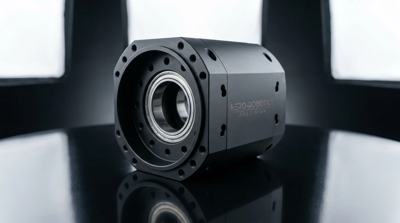 Caption: A 5-axis CNC-machined 7075-T6 aluminum robotic actuator housing with a bead-blasted black anodized finish. Alloyer delivers complex motor enclosures featuring concentric bearing bores and precise mounting faces, with standard Al 6061-T6 parts starting from $8.99 and 1-piece prototyping accepted.
Key Things to Know About CNC Machining for Robotic Actuator Housings
- Stiffness-to-Weight Optimization: Aluminum 7075-T6 is the industry baseline for bionic joints, offering steel-grade strength at one-third the density to optimize the dynamic response of the robot arm.
- Concentricity & Alignment: Multi-stage gear reduction assemblies require dual bearing bores to be concentric within 0.015 mm to prevent torsional binding and gear wear.
- Thermal Dissipation: Actuator housings act as primary heat sinks for high-torque frameless motors, requiring optimized surface area and thermal-conductive finishes like clear chem-film.
- Thin-Wall Integrity: Minimizing joint mass requires wall profiles down to 1.2 mm. These profiles demand advanced 5-axis tool paths and custom clamping to prevent thin-wall deflection during milling.
- Prototyping Agility: Embodied AI and robotic startups can iterate joint designs rapidly with Alloyer's 72-hour delivery, zero MOQ, and automated DFM reviews.
Why Robotic Actuator Housings Demand Specialized CNC Machining
Robotic actuator housings serve as the structural backbone of bionic joints, enclosing frameless brushless motors, harmonic or cycloidal gearboxes, high-resolution encoders, and communication controllers in a single compact envelope. Because these joints undergo rapid acceleration and sudden directional reversals, the housing must maintain absolute structural rigidity under dynamic torque loads.
Joint Kinematics and Structural Load Paths
During rapid bipedal locomotion or high-payload manipulation, actuator housings experience severe twisting moments. If the housing deflects by even 0.05 mm, the internal gear mesh becomes misaligned. This misalignment increases mechanical play (backlash), generates heat, and degrades the positioning accuracy of the robot. CNC-machined Aluminum 7075-T6 provides the necessary mechanical stiffness to isolate these deflection forces. For high-torque joints like the hip or shoulder pitch in heavy-duty robots, Ti-6Al-4V (Titanium Grade 5) is specified for its superior fatigue strength and stiffness, though it increases the machining cycle time by 4–5x compared to aluminum.
Compact Integration and Thin-Wall Deflection
To fit inside standard anthropomorphic limbs, actuators are designed with sub-millimeter clearances. This requires housings with wall thicknesses as low as 1.0 mm to 1.5 mm. Machining these thin walls presents a major CNC challenge: the workpiece tends to vibrate or "chatter" under the cutting force of the end mill, leading to dimensional drift and poor surface finish. At Alloyer, we mitigate this by using high-speed, light-radial-depth-of-cut tool paths and custom internal expansion fixtures that support the thin-wall walls during outer-diameter finishing.
Absolute Sealing and Environmental Protection
Autonomous mobile robots (AMRs) and humanoid systems often operate in dusty or wet environments, requiring IP65 or IP67 ingress protection. The actuator housing's mating faces must be machined with extremely flat sealing grooves (planarity within 0.02 mm) to host O-rings, and the surface must be treated to resist corrosion.
Material Properties for Robotic Actuator Housings
Choosing the right material represents the primary trade-off between thermal conductivity, structural weight, fatigue life, and CNC machining costs.
| Material | Density (g/cm³) | Yield Strength (MPa) | Elastic Modulus (GPa) | Thermal Conductivity (W/m·K) | Machinability | Cost Index* | Primary Actuator Application |
|---|---|---|---|---|---|---|---|
| Al 6061-T6 | 2.70 | 276 | 68.9 | 167 | Excellent | 1.0x | |
| Al 7075-T6 | 2.81 | 503 | 71.7 | 130 | Good | 1.5x | |
| Ti-6Al-4V | 4.43 | 880 | 113.8 | 6.7 | Poor | 8.0x | |
| PEEK | 1.30 | 100 | 3.6 | 0.25 | Fair | 15.0x | |
| POM (Delrin) | 1.41 | 65 | 2.9 | 0.23 | Excellent | 0.8x | |
| 17-4PH Steel | 7.80 | 1170 | 196.5 | 17.9 | Fair | 3.5x |
Technical Deep Dive: Critical Tolerances & Concentricity
Actuator performance is directly limited by the geometric dimensioning and tolerancing (GD&T) of its housing.
Bearing Bore Diameters (H7)
Bearings that support the motor rotor and gearbox output shaft require an H7 tolerance (+0.021/0 mm for a 18–30 mm bore). If the bore is machined too large, the bearing outer ring will slip, causing shaft runout and audible noise. If the bore is too small, the bearing's internal radial clearance is compressed, inducing excessive preload, heat generation, and premature actuator failure within a few hundred hours of operation.
Shaft and Rotor Concentricity
The concentricity between the motor stator seating diameter and the bearing bores must be held within 0.015 mm. Any eccentric offset introduces an asymmetric magnetic pull on the rotor, causing torque ripple and vibration. For integrated cycloidal gearboxes, concentricity offsets as small as 0.01 mm can reduce torque transmission efficiency by up to 12%.
Mounting Face Squareness and Planarity
The actuator mounting faces must be perpendicular to the rotational axis within 0.02 mm. Non-planar mounting faces introduce bending moments when bolted to the robotic arm links, causing internal stress, misalignment of the output shaft, and localized gear wear.
Tolerances and Surface Finishes for Precision Housings
| Housing Feature | Dimensional Tolerance | Surface Roughness (Ra) | Post-Processing Finish | Engineering Notes |
|---|---|---|---|---|
| Bearing Bores | H7 (+0.021/0 mm) | 0.8 μm | Bead Blast + Type III Hard Anodize | |
| Stator Seating | H6 (+0.013/0 mm) | 0.8 μm | Type II Anodize or Chem-Film | |
| Mating Face O-ring Groove | ±0.05 mm | 1.6 μm | Bead Blast + Hard Anodize | |
| External Gear Spline Interface | h6 (+0/-0.013 mm) | 0.4 μm | Ra 0.4 μm super-finishing | |
| Threaded Helicoil Insets | 6H (Standard) | 3.2 μm | None (Clean threads) |
DFM Checklist for Robotic Actuator Housings
Designing for manufacturability (DFM) drastically reduces machining cost, setup time, and tool wear while ensuring structural integrity.
1. Avoid Sharp Internal Corners
Sharp internal vertical corners cannot be machined with rotating CNC end mills. Design internal corners with a radius of at least 1.5 times the pocket depth to allow standard, rigid end mills to route the pocket efficiently, minimizing tool chatter and breakage.
2. Optimize Thread Engagement in Aluminum
Because aluminum has a lower shear strength than steel fasteners, thread engagement must be at least 2.0 times the nominal bolt diameter (e.g., a thread depth of 6 mm for an M3 screw). For joints subjected to frequent disassembly, integrate stainless steel Helicoils to prevent thread stripping.
3. Implement Standard Wall Thicknesses
While weight reduction is critical, maintaining a minimum wall thickness of 1.2 mm in Aluminum 7075-T6 and 2.0 mm in PEEK ensures that the walls do not deflect or buckle during high-feed milling operations.
4. Standardize Tooling Access Radii
Design internal radii using standard tool diameters (e.g., 3 mm, 4 mm, 6 mm). Specifying non-standard radii forces the CNC machinist to use custom tooling, which increases setup times and per-part costs.
Cost & Lead Time Reference for Actuator Batches
| Material | Prototyping Batch (1–5 pcs) | Mid-Volume Batch (50–200 pcs) | Typical Lead Time | Cost Reduction Strategy |
|---|---|---|---|---|
| Al 6061-T6 | $120–$180 / pc | $45–$70 / pc | 3–5 days (Express) | |
| Al 7075-T6 | $160–$240 / pc | $65–$95 / pc | 5–7 days (Standard) | |
| Ti-6Al-4V | $800–$1,200 / pc | $350–$500 / pc | 7–10 days | |
| PEEK | $350–$550 / pc | $150–$250 / pc | 5–7 days |
Frequently Asked Questions
What is the best material for a highly stressed robotic ankle actuator housing?
For joints experiencing high impact forces, we recommend Aluminum 7075-T6 with a Type III Hardcoat Anodize. It provides a yield strength of 503 MPa, which is nearly double that of Al 6061-T6, while keeping the density at 2.81 g/cm³. For military-grade or deep-sea ROVs where maximum stress and corrosion resistance are required, Titanium Grade 5 (Ti-6Al-4V) is the premium alternative.
How does Alloyer achieve tight H7 tolerances on bearing bores?
We utilize precision carbide reamers and fine boring heads on high-speed 5-axis Haas machining centers. Our quality control department verifies every single bore diameter using calibrated go/no-go plug gauges and coordinate measuring machines (CMM) in temperature-controlled environments to ensure the dimensional variance stays within +0.021/0 mm.
Should I choose clear chem-film or anodizing for my actuator housing?
Specify Type II or Type III Anodizing for external surfaces that require wear and corrosion resistance. However, for internal stator mating surfaces where electrical grounding or maximum heat dissipation is critical, we recommend clear chemical conversion coating (chem-film). Anodizing creates an insulating oxide layer that restricts electrical conductivity and slightly decreases thermal transfer.
How do I design internal wire routing channels to minimize weight and space?
We suggest integrating internal wire conduits directly into the housing geometry during 5-axis CNC setup. Ensure that all internal routing exits feature rounded chamfers or radii (minimum 1.0 mm) to prevent wire insulation from chafing under dynamic robotic movements. Alternatively, low-friction POM (Delrin) sleeves can be inserted into the channels.
Related Guides for Robotics Engineers
- CNC Machining for Humanoid End-Effectors: Design, Materials & DFM Guide
- CNC Machining for High-Precision Robotic Gearboxes: Materials & DFM Guide
- CNC Machining for Collaborative Robots (Cobots): Precision for Human-Robot Interaction
- CNC Machining for AGVs & AMRs: Heavy-Duty Structural Engineering Guide
- CNC Machining for Robotic Arms: Materials, Tolerances & DFM Guide